In a very next post, I will explain in detail the implementation of a multiplexer (¹) Miniplex-2USB ShipModul's website. But before dismantling the electrical panel and taking out the toolbox, it is better to understand the subtleties of a connection that, at first glance, seems very simple, and yet can quickly become… a real headache.
The theory
Le standard NMEA 0183 specifies that the input and output ports of transmitters and receivers must be differentials. This means that data is transported using an electric current on two wires, separated from the ground. The voltage oscillates between 0 and 5 volts, and both wires are in opposite phase. When one is at 5V, the other is at 0V, and vice versa.
Such a system has two advantages :
- Less susceptible to interference : a differential receiver only detects the voltage difference between the two conductors, but not the absolute value of the voltage. Interference has no influence on this measurement.
- Less generator of interference : a differential system produces little interference on high frequency systems. The magnetic fields generated by each wire are in phase opposition and do not affect other nearby conductors.
This would all be great if all manufacturers adhered to this standard. Well, isn't it !
To save a few dollars, some of them prefer to rely on the quality of the conductors or even the presence of opto-couplers recommended for the galvanic isolation of electronic equipment (²).
Thus, their instruments are simply equipped with NMEA inputs and outputs asymmetrical, composed of a single data conductor, where the return signal is transported on the common negative connection (ground). Technically, the difference lies in this current return, common to all instruments and supply, with the risks of strong voltage variations that this entails, and therefore disruption of the transported data.
The practice
The boater, his screwdriver in his hand, will then meet with four possible connections to be made with its own instruments :
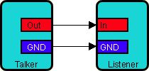
- Differential to Differential

This is the normal configuration of the NMEA standard. Valid in both directions : talker to listener and vice versa.
- Single-ended to Single-ended

This is the worst configuration, the negatives are connected, but relies to common supply ground.
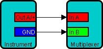
- Sigle-ended to Differential

In this configuration, It is important not to link the return of the B receiver to a power ground close to the multiplexer, but directly to the ground connector of the talker, itself connected to its own ground. This prevents any supply currents to disturb the data.
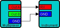
- Differential to Single-ended

Only data connectors are connected (A vers A ou RX). Return connector B remains free. The return through the ground of both listener and talker. The wire must be the shortest and most straight on. Above all, do not connect the talker return connector (B) to ground, it would be short-circuited.
- Differential (Multiplexer) to multiple listeners

If multiple receivers are connected to a talker, as for a multiplexer NMEA OUT output, it is necessary to establish the connections according to the different types of instruments, following the diagram above. The different combinations can coexist.
Once well understood and integrated these schemes, you can boldly take back your screwdriver, NMEA will have no secrets for you.
Sources of text and illustrations : ShipModul website. Freely translated and adapted.
–––
(¹) For total beginners in NMEA, start by reading the document NMEA and Multiplexers.
(²) An opto-coupler is a device that carries information using light instead of electricity, preventing parasitic currents from flowing between the instruments and the multiplexer. These currents can damage equipment or interfere with radio signals, galvanic isolation of inputs is required by the NMEA standard 0183.
–––

